While analizing the process that you have to automate you always have many conditions to respect for the safeness of the equipments, of the operators and of the process itself.
What is an Alarm
An alarm is a condition of non-safe state of the machine.
Depending on the impact on the process, it can be:
- Blocking
- Not blocking
An alarm can be connected to an input sensor, but it’s never the sensor itself; alarms are generally stored in words (16-bits registers) and displayed in the HMI, as well as used in the program as conditions to grant the safeness of the process.
What is interlocked equipment
Interlocked equipment, like motors or valves, is an equipment that has a protection circuit (real or logic) that interdicts the activation of the equipment if at least one danger condition is met.
Alarms with ladder logic
When i write alarms and interlocks i always use the same structure, that consists in many words where every bit corresponds to an alarm; this structure is almost a standard for many operators panel and has many good points but some drawbacks too (a drawback is that you can analize block of alarms comparing and masking entire words, that can be cheaper to write, but harder to understand when reading or debugging).
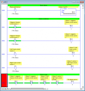
This is a basic sample on how i write an alarm block:
When writing alarms in this way the first segment must be always the reset block. This because even if you reset all the alarms pushing the reset button, if one fault condition is active, the alarm will be setted again few segments later, resulting in a still active alarm at the end of the program.
The last part is a recap of all alarms, really useful while debuggin because you can notice instantly what’s going on just by watching 1 segment.
The first bit of the word alarm has been chosen as “no active alarms” because usually:
- Alarms starts from number 1 and continues, so it’s no use to have an offset among alarms and bits
- This bits triggers all the alarms-screens and alerts on HMI and scada.
This is just a basic explanation, but you can find a more detailed explanation about fault logic here: http://www.contactandcoil.com/rslogix-5000-tutorial/create-fault-logic/
Writing interlocked equipment in ladder logic:
Once you detected the fault conditions for your plant, you should use alarms and other conditions inside interlocks to avoid dangerous operations.
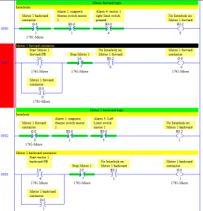
I usually write outputs logic and interlocks in this way:
Same as alarms, interlocks must be above the segment that declares the output coil condition and the interlock bit should include every condition that stops the motor.
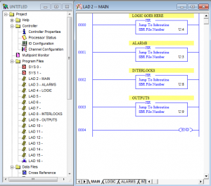
A common strategy that peoples uses when outputs grows in number is to have a block dedicated to interlocks that comes exactly before the block dedicated to output, like this:
When writing interlocks in this way debugging become really easy, because you can just navigate with 1 or 2 clicks of the mouse to the cause of interlock without having to analize a lot of logic.
You can download a sample application for RsLogix 500 here: https://www.mesta-automation.com/Downloads/alarms%20and%20interlocks.rar
 Mesta Automation A blog about WPF, C# and PLC software development


what do contacts with a green background mean? Are they in the opposite state of what is visually represented. As in is an N/O contact with a green background actually a N/C contact?
Green is the status of the contact: if it’s green, the current is flowing, if it’s white, the contact is open.
NO Contacts are represented like this -] [-
NC Contacts are represented like this -]/[-
hi sir,
I am working as an electrical officer/ETO in merchanty navy with dynacom tankers management. We have a hard ware problem with the allenbradley micro logix 1400 PLC. The I/N 2 of the PLC grounded and that is for motor overload alarm.But there is an interlock with all alarms .so we cant’ start the system until we remove this alarm.I can’t connect cable (+24 ) in IN/2 as it was shortd(grounded). So please tell me
1) Can I remove the interlock for this spesific alarm comming from IN/2 using MODBUS TCP
(OR)
2)can I programme IN/2 to shIft to another input port (in/19)
You can program the software to shift the address of the broken input, but you need the software (RsLogix 500).
You can also probably force the input by using the LCD screen, but i don’t remember how. You better call Rockwell Automation support and ask there for help.
thans for ur prompt reply sir.I allready downloaded rs logix 500. Can you tell me how to connect my pc to micrologix 1400 PLC using ethernet and how to edid the programme by changing in put from IN/2 TO IN/18(free).
There are user manuals for this. Google “getting started with RsLogix 500” and start from chapther 2. If you encounter issues, please use some forums like plctalk.net, where there are experts that can help you. This website is just a personal blog and not a sobstitute for Rockwell Assistance.
I need to create an alarm which does two things
1. send signal to a hooter and make sound , but this can be stopped by pressing a push button .
2. make an indicator lamp glow on the control panel , this should be glowing as long as the fault is not cleared .
i think the hooter will be a common hardware and will sound when some other fault arises
This article explains how to separate the cause of the alarm from the notification lights, sounds and HMI indicators.
If you have an alarm, you need a single bit that is 1 or 0, depending if the alarm is on or off. This bit can be resetted depending on some conditions and it is usually activated from sensors or other equipment in fault.
This bit, togheter with other alarms bit in OR condition, permits you to to command both the light and the sound.
Something like:
IF(alarm_bit == 1) THEN alarm light = 1;
IF(one_shot(alarm_bit) == 1) THEN SET sound = 1;
IF(shutoff_sound_button pressed) RESET sound = 0;
Also using this approach you can use alarm bit to interlock equipment in case of dangerous conditions.