The latest PLC Allen Bradley Micrologix 1400 is provided with Modbus TCP and RTU. This is a powerful feature and with this post i explain how to enable and how to use it.
To configure the Modbus communication you need to know at least the basic information about Modbus protocol.
Quick overview of Modbus protocol
Modbus protocol can be used with serial cables (Modbus RTU: RS232 or RS485) or with ethernet cable(Modbus TCP).
Modbus TCP architecture is client – server (like for websites, you with the browser are the client that ask information to the server, and the server reply). Modbus TCP devices can be both client-server and the protocol is multi-master, so every device can start the communication.
Modbus RTU architecture is master – slave (master is the client, slave is the server). The only device that can start a communication is the master and there can be only one master (usually a supervisor) and as many slave as you want. Every slave has a “Node address”, so the master can send packet to a single slave. Master does not have the Node address.
The registers
You have 4 types of registers:
- 2 are read-only (for bits and integers)
- 2 are readable and writable (for bits and integers)
Boolean block es. B3:
Read Only registers are called Contacts.
Read/Write registers are called Coils.
Numeric block es. N7:
Read Only registers are called Input Registers.
Read/Write registers are called Holding Registers.
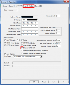
Enabling Modbus TCP:
Important note: once you flag Modbus TCP and save the configuration, you should powerup the PLC again.
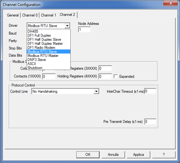
Enabling Modbus RTU Slave
To enable Modbus RTU you have to configure channel 2 as Modbus RTU Slave.
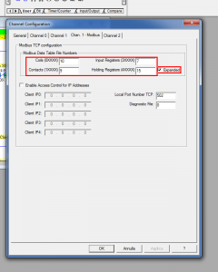
Block configuration:
With this configuration i have:
B9: read-only
B10: r/w
N7: read-only
N15: r/w
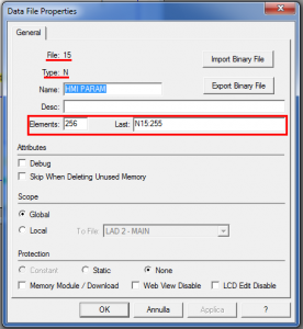
Expanded flag: this flag permit to use 4 more N registers contigous to N15 in order to expand the holding registers area.
To enable expanded registers you need to declare N15 – N16 – N17 – N18 – N19 and to set all the registers words to 256.
Sample code
You can download a sample application from here.
The program has been tested with the Modbus TCP tester that you can find at http://www.codeproject.com/Articles/16260/Modbus-TCP-class .
 Mesta Automation A blog about WPF, C# and PLC software development


Hi Mesta
Thanks for the notes much appreciated.
What version of RSLogix500 are you running? I am running 8.10.00 and noticed that the Modbus selection is not available. I havent installed a modbus software driver into the PLC, not sure if I have to.
Regards
Gray
I was running RsLogix 500 version 8.40.00.
Please note that Modbus protocol is available only on Micrologix 1400 Ser. B.
Micrologix 1400 Ser. A doesn’t provide Modbus communication.
Is there any way to connect mod bus with ser a
8.3 r later
Hello Mesta,
Do you know how many client connections a Micrologix 1400 Ser. B. can handle?
I try to connect to a PLC from a 2nd PC and it does not work.
It depends if it’s Modbus TCP or RTU.
For Modbus TCP i connected up to 3 computers time ago, but i never tried with more.
For Modbus RTU it depends if the Micrologis is set as master or slave.
Hi mesta,
I have Micrologix 1400 Ser B PLC.I have to establish a communication with Modbus TCP & RTU.How to use RSLinx Classic to configure driver for the same?
RsLinx can’t communicate in Modbus, it uses the proprietary protocols of RA.
The ethernet port of Micrologix can communicate with 2 or 3 protocols simultaneously, and the simil-Ethernet/IP is the default, and you can choose what other protocol you want to communicate with, in your case Modbus.
So with RsLinx you set Ethernet Devices (not Ethernet/IP, it will not work) and you can communicate with RsLogix, while with your applications and other plcs you communicate in Modbus.
Hi Mesta,
What about Modbus RTU???What I am supposed to select in Rs-Linx while configuring ML1400 Ser B through Modbus-RTU?I have done channel configuration through RS-Logix 500.But it is unable to establish a communication link.
Kindly revert back.
I don’t remember if the serial port of Micrologix can talk 2 different protocols. If it does, then you have to select DF1 in RsLinx. If it can communicate only Modbus RTU, you have to use the other serial port or connect through the ethernet port.
Hi Mesta,
Iam an newbie in .net,basically from PLC,SCADA domain.
Big fan of ADVHMI, Now can some one share me a project where the real time data from PLC can be logged to sql server.
I want to make a screen for data and another one for reports.
Does someone have done this in advanced hmi.
Thanks
Krishnamoorthy
Hello Mesta:
I’m working with web server embed on Micrologix 1400 PLC and RSLogix 8.40.
I monitored directory enabled and N7: 0, (eg)
Using codes <ABDRT-xxx) but only for reading, my question is:
Is there any code with which I can now write to that block (N7: 0)?
Thank you.
I have no experience of working with embedded webserver of Micrologix 1400. In the projects based on ML-1400 was using Ethernet/IP, OPC client or Modbus TCP protocols; with all of them i was using C# or ANSI-C compilers.
HI mesta
do you have a sample rslogix500 plc program for modbus TCP/IP communication pls send me on shridharhanamannavar@gmail.com
Actually i don’t have a working sample, but you can test that if your program works by using the Modbus client that you can find on http://www.plcsimulator.org/
Have you got solution for your above said question? i am working on the same…if you have any details please share with me also….
Thankx…
Actually I don’t have the hardware needed to make tests, so i can’t make a program and assure you 100% it works. At the time that i wrote the article, i was working on a project where the ML1400 was connected via Modbus TCP with other PLCs and it was working.
My mail address is rohan_984@yahoo.com
I make. All the configuration as you said but there is connection timeout by a network this message is coming out
Is this possible the Chanel 0 make mod bus RTU and Chanel 1 make mod bus TCP in same plc
Mesta, same question as pdmaraj: is it possible to use both Channel 0 (Modbus RTU) and Channel 1 (Modbus TCP) at the same time? My goal is to read/write data on both channels as I do have a RS485 network and the PLC communicates with the scada using modbus TCP… THANKS!
According to RsLogix, it seems that you can use Modbus RTU on channel 0. At least in my version you can set Modbus on the protocol instead of DF1.
Hi, do you have any examples showing the use of Modbus RTU Master? I have an A series 1400 and I’m trying to configure a RTU master
hi i want to take Delta DTA4848 Temperature Controller Data on Allen Brdley ML1400 or ML1100 PLC…..Any Body can please tell me the full procedure
You have to set up messages. Google for micrologix messaging modbus, there are plenty of examples.
While using a MicroLogix 1400 as a serial Modbus RTU slave I am not able to find the location of the discrete inputs (contacts). They are not showing up in the 10001-19999 range as documentation suggested. Do you have any ideas? Thanks.
Did you try to check the address from 0000 to 9999? Because usually the first number is the function identifier, and 1 means “contact address area”.
There are different functions for each address area (1-2-3-4-etc).
DEAR ALL,
i am facing problem to access data of masibus temperature scanner through modbus TCP/IP on ML1400. If any one of you have sample application of ML1400 communication with any device on modbus TCP/IP please send me at chauhan.singhraj@gmail.com
Please help me!!!
how to set up the Ml 1400 rev. b by modbus TCP like a client?
If ML1400 has to read from a Modbus server, you can do it with messages. It shouldn’t be difficult, just run a search on google.
hi
i want to communicate Micrologix 1400 to compact Logix on prosoft wireless is it possible
yep just use the MSG instruction.
hi Mesta .
My goal is to read/write data , i have a Modem network and the PLC communicates with the scada using modbus TCP ethernet
My PLC micro 850the rockwell .
how to connect micrologix 1400 with vegacontrol input/output modules via modbus?
Hi Mesta,
I won’t help
I am using 1400 series B
And on that I am doing barcode scanner preject
South how can I configure barcode scanner to plc using RS232 cable
Plz send me information about that..
Email
rohan.tamboli07@gmail.com
i want to connect ML1200 to scada software using modbus address. how can i do it?
Manuals from Allen Bradley are really good. http://literature.rockwellautomation.com/idc/groups/literature/documents/rm/1762-rm001_-en-p.pdf
HI,
I Have a ML1200 series C PLC. can i configure modbus communication for this? If yes then How?
i want connect ml1200 with modbus communication
http://vdt-automation.de/docs/ml1500_modbus.pdf
i have use this pdf but i cant read values from plc to modscan 32
I have a ML1400 Class B. I have data on it I can see the data on the WEB I try to read the data. I used for a test code from Ni and others too. In all cases I can connect to the PLC. But always get an error of wrong address. How I can know the data address for N38:45 Etc. I need the starting address. I can provide a screen shot from Both the Web and from the program I tried. Can anyone help please ?
I solved the issue and now I can access the ML1400. using the VB6 sample code v2. I have to to read only the Numeric data.
I my case I have N38 till N42 each have 256 regs defined. In the demo there is a limit of 16 regs I removed the limitation and made correction to keep all the data (for more then 16 regs). I find out that I can not read at once more then 123 regs. Any Idea how I can remove this limit ?
That’s a limitation of Modbus. You have to do multiple requests.
How to communicate micrologix 1400 PLC with Raspberry Pi
I am trying to setup the master and slave for my ML1400 PLC using 2 core ( Tx-1 & Rx-1) RS 485 modbus communication. I received the data as my ML1400 channel 0 set as Modbus RTU master. I am trying to send my data with the same RS485 communication. How to setup the message instruction for that.
Hello I couldn’t download the sample program . If I just had a b:3/0input controlling an output O:0/0 in micro logix 1400 modbus tcp ip how would I address the b3/0 on a maple system hmi 520-c I it is comunicating correctly but I am new to the hmi 520-c any help would be appreciated
hello
i have a recorder with tcp/ip modbus configuration. problem is that data is shown on modscan but not come in ml1400 series B plc. i did all the setting which you suggest but not successful. please help me out.and give me some example for tcp/ip modbus configuration for ML1400 plc.
waiting for your reply.
email id is vishal3159@gmail.com
Hello Mesta, I’m newbie using AdvanceHMI. I was download AdvanceHMI software but when i run, i got information about missing library extension. Would you give me AdvanceHMI completely in my email software.solution.industry@gmail.com.
I will try connected to Alan Bradly Micrologic 1400-1766 using ethernet.
Hi , we not able to save data, then we changed battery. However the screen shows error message ” communication with PLC FAILED ” could you please advise how to fix it. Many thanks in advance